What are purpose and scope of inspecting radio-brightening television equipment for medical use in Vietnam?
What are purpose and scope of inspecting radio-brightening television equipment for medical use in Vietnam? What are regulations on content of process of inspecting radio-brightening television equipment for medical use in Vietnam?
I have questions about the above issues, I hope to be answered according to latest provisions of the law in Vietnam.
What are purpose and scope of inspecting radio-brightening television equipment for medical use in Vietnam?
In Section I, Appendix III.8 issued together with Circular 08/2022/TT-BKHCN (effective from 22/7/2022) stipulating purpose and scope of inspecting radio-brightening television equipment for medical use as follows:
1. Purpose
This procedure specifies the verification of television illuminant X-ray equipment for medical use.
2. Scope and subjects of application
This procedure applies to organizations and individuals participating in the service of inspection of television illuminant X-ray equipment for medical use; state management agencies and other relevant organizations and individuals.

What are regulations on content of process of inspecting radio-brightening television equipment for medical use in Vietnam?
According to Section I.3, Appendix III.8 issued together with Circular 08/2022/TT-BKHCN (effective from 22/7/2022) inspecting radio-brightening television equipment for medical use contains the following procedure:
3.1. diagram
|
1. Prepare equipment, tools and supplies |
=> |
2.1. Visual inspection |
=> |
3. Inspection result report |
|
| |
| |
|||
|
2.2. Check patient table movement accuracy |
4. Inspection certificate |
|||
|
| |
||||
|
2.3. check beam time accuracy |
||||
|
| |
||||
|
2.4. Check exit dose |
||||
|
| |
||||
|
2.5. Check effective focal size of the X-ray tube |
||||
|
| |
||||
|
2.6. Check dose rate at the input of the imager |
||||
|
| |
||||
|
2.7. Check image quality |
3.2. Explain
The steps in this process are summarized based on QCVN 16:2018/BKHCN.
Step 1: Prepare equipment, tools and supplies
Step 2.1: Check the appearance
- Check X-ray equipment information.
- Check the mode switch and instructions.
- Check the mechanical operation of the systems.
- Check the warning signal when the device emits rays.
- Check the show time warning function.
- Test the ability to control beam remotely.
Step 2.2: Check peak voltage
- Check peak voltage accuracy
+ Use 2mm thick copper X-ray absorption plate to cover the imager.
+ Fix the peak voltage measuring device at the center of the radiation field, away from the focus of the X-ray bulb at the distance recommended by the manufacturer of the measuring device.
+ Focus the beam so that the radiation field covers the entire radiation sensitive area of the measuring device.
+ Fix the emitter current, perform ray emission corresponding to each changing peak voltage value in the commonly used working range.
- Check repeatability of peak voltage
+ Use 2mm thick copper X-ray absorption plate to cover the imager.
+ Fix the peak voltage measuring device at the center of the radiation field, away from the focus of the X-ray bulb at the distance recommended by the manufacturer of the measuring device.
+ Focus the beam so that the radiation field covers the entire radiation sensitive area of the measuring device.
+ Perform a minimum of 3 rays with the same peak voltage value and commonly used emitter current.
Step 2.3: Check primary beam filter
- Check the value of the additional filter (if any) of the X-ray device.
- Fix the dose rate measuring device at the center of the radiation field, away from the focus of the X-ray tube at the distance recommended by the manufacturer of the measuring device.
- Focus the beam so that the radiation field covers the entire radiation sensitive area of the measuring device.
- In case of using a measuring device that displays the HVL . value
+ Perform beam emission.
+ Read the HVL value and peak voltage on the measuring device.
- In case of using a measuring device that does not display the HVL value to evaluate X-ray equipment with manual peak voltage setting mode:
+ Set fixed peak voltage and commonly used emitter current.
+ Perform beam emission without placing the aluminum filter between the emitter and the measuring device, record the dose rate value on the measuring device.
+ Place a 1 mm aluminum vial plate between the emitter and the measuring device, perform beam emission, record the dose rate value of each measurement.
+ Repeat the irradiation with increasing thickness of aluminum filters until the dose rate is reduced to less than 1/3 of the dose rate value in the absence of the aluminum filter.
+ Graph the distribution of dose rate values according to the thickness of aluminum filters.
+ HVL is the value on the horizontal axis determined from the coordinates at which the value on the vertical axis is 1/2 of the value corresponding to the dose rate value when there is no aluminum filter.
- In case of using measuring device that does not display HVL value to evaluate X-ray equipment operating with automatic dose rate control mode
+ Place 5 mm of aluminum between the measuring device and the imager.
+ Perform beam emission without placing the aluminum filter between the emitter and the measuring device, record the dose rate value on the measuring device.
+ Gradually reduce the thickness of the aluminum filter between the measuring device and the imager (in steps of 1 mm), respectively, gradually increase the aluminum thickness between the measuring device and the emitter (in steps of 1 mm); perform irradiation, record the dose rate value on the measuring device. Repeat this step until the measured dose rate is less than 1/3 of the dose rate value when there is no aluminum filter placed between the measuring device and the emitter.
+ Graph the distribution of dose rate values according to the thickness of aluminum filters.
HVL is the value on the horizontal axis determined from the coordinates at which the value on the vertical axis is 1/2 of the value corresponding to the dose rate value in the absence of the aluminum filter.
Step 2.4: Check beam condenser
- Set SID to the largest. Fully open the beam focal point.
- Place the film cassette as close to the surface of the imager or as close as possible.
- Perform beam generation with low peak voltage or use automatic dose rate control.
- Measure and record the shape and size D of the radiation field on the film according to the conventional shape of the radiation field as shown in Figure 8.1.
- Calculate the area of the radiation field according to the following formula: Area = D 2 x k (1)
The size value of the radiation field (D) and the corresponding constant k are conventionalized according to the shape of the radiation field according to Figure 8.1.
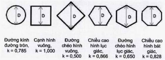
Figure 8.1. Geometries of the radiation field, the field of view and the corresponding k value
- Remove the film cassette and place the test instrument of known dimensions (dcheck, real ) as close to the imager surface or at the closest possible distance.
- Perform ray tracing and image observation on the screen.
- Measure and record the size of the test instrument (dcheck, measure), the size of the field of view (dlook, measure ) on the screen. The actual size of the field of view (Dlook, real ) is calculated by formula (2).
D look, real = D look, measure x dcheck, real / dcheck, measure (2)
Note: If the test instrument is not placed close to the imager, the dimensions need to be adjusted according to the distance between the test instrument and the imager.
- Calculate the actual field of view area according to formula (2).
Repeat the above test steps with different fields of view, including maximum and minimum field of view.
Repeat the above checks with the smallest SID (if it can be changed).
Step 2.5: Check the output dose rate
- Set peak voltage and emitter current to maximum used in normal mode. In the case of X-ray equipment operating with automatic dose rate control, use an X-ray absorber plate with a minimum thickness of 2 mm of lead to cover the imager.
- Set SID to the smallest.
- Place the dose rate measuring device at the center of the radiation field, corresponding to the position described in Table 3 of QCVN 16:2018/BKHCN. If the measuring device is located at another location, the result can be calculated according to the inverse square of the distance law.
- Perform beam emission and maintain beam emission until the measured value displayed on the measuring device stabilizes and record the dose rate value on the measuring device.
In the case of high-mode X-ray equipment ( boost mode), repeat the test with this operating mode.
Step 2.6: Assess the input dose rate of the imager
- Set up X-ray equipment to operate with automatic dose rate control.
- Set the SID as recommended by the instrument manufacturer. Remove the anti-scatter mesh. In case the anti-scatter net cannot be removed, the dose rate measurement result must be divided by the attenuation coefficient through the anti-scatter mesh (if this factor is not available, the measurement result is divided by 1.4).
- Place the measuring device at the center of the radiation field, close to the surface of the imager or at the closest possible distance.
- Place an X-ray absorber plate equivalent to 2 mm thick copper between the test tool and the emitter.
- Perform beam emission and maintain beam emission until the measured value displayed on the measuring device is stable and record the dose rate value on the measuring device.
- Repeat the test with different set field of view sizes.
Step 2.7: Check image quality
- Set SID to minimum. Set up X-ray equipment to operate with automatic dose rate control.
- Place the high-contrast resolution tester close to the imager surface, the center of the test instrument coincides with the imager's center.
- Place the X-ray absorber plate with the thickness recommended by the test instrument manufacturer.
- Set the smallest radiation field size while ensuring the radiation field covers the entire test instrument.
- Perform irradiation and observe the image of the test instrument on the screen.
- Repeat the test with different fields of view. In the case of X-ray equipment using an FPD imager, it is only necessary to perform the examination with one field of view.
Step 3: Report the inspection results
- The inspection results must be made into an inspection record with all contents according to Form 1. The inspection record is issued together with QCVN 15:2018/BKHCN.
- The inspection minutes must be approved and signed and stamped (if any) by the members:
+ The representative of the establishment using the X-ray equipment or the person authorized by the establishment.
+ The person assigned by the establishment using the X-ray equipment to participate and witness the inspection.
+ The person performing the test.
- Based on the data of the test results in the inspection report, the person performing the inspection must calculate and evaluate the working characteristics of the X-ray equipment according to the instructions and make a report. audit assessment according to Form 2. Report on inspection results issued together with QCVN 16:2018/BKHCN.
Step 5: Certificate of inspection
- The certificate of inspection is only issued to the X-ray equipment after it has been tested and concluded to meet the acceptance requirements.
- When the inspected X-ray equipment meets the acceptance requirements, the inspection organization must issue an inspection certificate within 15 working days from the date of approval of the inspection report at the establishment according to the Form 3. Certificate of inspection issued together with QCVN 16:2018/BKHCN.