What is Vietnam Standard TCVN 4365: 1986 on Straight-sided splines – Load capacity calculation methods about?
What is Vietnam Standard TCVN 4365: 1986 on Straight-sided splines – Load capacity calculation methods about?
Vietnam Standard TCVN 4365: 1986 was converted in 2008 from Vietnam Standard with the same serial number to National Standard as prescribed in Clause 1, Article 69 of the Law on Standards and Technical Regulations 2006 and Point a Clause 1, Article 6 of the Government's Decree No. 127/2007/ND-CP dated August 1, 2007, detailing the implementation of several articles of the Law on Standards and Technical Regulation. Concrete:
In Clause 1, Article 69 of the Law on Standards and Technical Regulations 2006:
Transition provisions
1. Vietnam standards and branch standards already promulgated under the 1999 Ordinance on Goods Quality and under other laws and ordinances shall be reviewed and converted into national standards or national technical regulations.
At Point a, Clause 1, Article 6 of Decree No. 127/2007/ND-CP:
Review and conversion of standards of Vietnam into national standards
1. The Ministry of Science and Technology shall preside over and coordinate with the ministries, ministerial-level agencies, and concerned Governmental agencies to review the standards of Vietnam that have been issued under the 1999 Ordinance on Goods Quality and under the laws and other ordinances to establish the following lists:
a) Vietnam standards not required to be amended, supplemented its contents when converted into national standards;
...
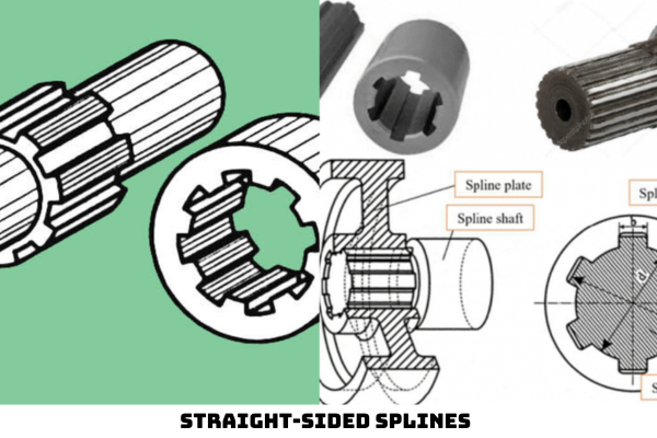
Vietnam Standard TCVN 4365: 1986 applies to straight-sided splines with gears, couplings, and other details.
Vietnam Standard TCVN 4365: 1986 does not apply to straight-sided splines of shafts with belt wheels or with intermediate gears and special straight-sided splines used to compensate for deviations or non-coaxiality of axes.
Vietnam Standard TCVN 4365: 1986 specifies the method of calculating splines according to stamping stress and wear strength indicators to determine load capacity.
What are the general provisions specified in Vietnam Standard TCVN 4365: 1986?
Under the provisions of Section 1 Vietnam Standard TCVN 4365: 1986, there are the following general provisions:
- The load capacity of the spline is determined according to the minimum value of the two values obtained through the calculation of stamping stress and wear strength.
- The calculation of stamping stress and wear resistance should be consistent with the limit state of the straight-sided spline. Coupling-type splines that only bear torque loads are not subject to wear strength. For splines subjected to short-term overload during the working period, the teeth must be further tested for storage stress at that overload level.
- Calculation of the stamping stress to be carried out for splines with increased working surface strength (tempering, carbon permeability) must be calculated at the initial stage before clearing; For splines with non-durable working surfaces or high tempering surfaces and ram, it must be calculated at the stage after clearance. In this case, it is necessary to take into account the decrease in stress concentration after clearance. Calculation of wear resistance is carried out in the period after clearance.
- In cases where wear is practically not allowed, further calculations of abrasion-free working must be carried out in an unrestricted large number of load cycles.
- For splines in mass-fabricated machines, especially large load-bearing machines or machines working in special conditions that have had their own research or have sufficient experience in using permissible stress calculation parameters or safety factors selected based on such data.
What are the guidelines for determining the load capacity under the Vietnam Standard TCVN 4365: 1986?
Based on the provisions of Section 2 Vietnam Standard TCVN 4365: 1986, the method of determining the load capacity is shown as follows:
2.1. Calculation of stamping stress for splines according to formulas:
(1) 
(2) 
or (3) 
where (4) 
2.2. Calculate the wear strength for splines according to the formulas:
(5) 
or [Mx] = SF.l. [s]m (6)
where (7) 
The working condition of the spline is abrasive free from abrasion at an unlimited large number of load cycles.
(8) 
Where:
[s]km = 0.028 HB, MPa (0.002 8 HB, kG/mm2) – for non-thermal teeth.
[s]km = 0.032 HB, MPa (0.003 2 HB, kG/mm2) – for my teeth and high ram.
[s]km = 0.3 HRC, MPa (0.03 HRC, kG/mm2) – for teeth that are tempered.
[s]km = 0.4 HRC, MPa (0.04 HRC, kG/mm2) – for carbon-permeable teeth.
The original data used to identify the values in formulas (1)–(8) is introduced in Tables 1 through 6 and indicates letter symbols. When calculating non-critical straight-sided splines, it is permissible to use the average permissible stress [s]m according to Table 2 of the Appendix
Thus, the method of determining the load capacity is calculated according to the above guidelines of Vietnam Standard TCVN 4365: 1986.
In addition, Vietnam Standard TCVN 4365: 1986 also indicates the following letter symbols:
Geometric features of the spline
d – inner diameter of sewing, mm;
D – outer diameter of the shaft, mm;
z – number of teeth;
fb – nominal height of the beveled edge on the toothed shaft, mm;
FC – nominal height of the beveled edge on toothed sewing, mm;
l – working length of the spline, mm;
LX – Geometric characteristics of torsional hardness, mm4.
Geometric characteristics of gears installed on shafts
DW – divider ring diameter (for bevel gears it is average diameter), mm;
e – displacement of the mean plane of the toothed rim relative to the mean plane of the toothed sewing part, mm;
aw – the matching angle of the transmitter, degrees;
b – angle of inclination of teeth, degrees;
[Mx] – permissible calculated torque (the largest value of long-acting moments), Nmm;
[Mxmax] – the maximum allowable torque is transmitted through the coupling at instantaneous maximum loads (e.g. when opening the machine), Nmm;
F – long-acting computational force on the spline, N;
Fv – internal ring force that articulates teeth, N;
Fk – glass direction force in tooth articulation, N;
Ft – axial force in tooth articulation (for inclined gears and tapered teeth), N;
No – number of cycles with base convention load;
t – the calculated life of the transmitter, hours;
NT – calculated rotational frequency, 1/min;
c – torsion-resistant specific hardness of the spline, 
Characteristics of the material
HRC – hardness on the Pulven scale of the tooth surface;
HB – hardness on the Brinen scale of the tooth surface;
G – Modulus of elasticity of the material as a shaft when sliding, MPa.
Stress on teeth
s – average stress on the working surface, MPa;
[s] – the average allowable stress when calculating the stamping stress, MPa;
[s]km – the maximum allowable stress under non-worn working conditions, MPa;
[s]m – average allowable stress when calculating wear, MPa.
LawNet